| Model 701 & 711
 These instruments are full featured Strain Gage Conditioners/Readouts; the Model 701 handles one and the Model 711 handles two transducers. Both provide fast, accurate data for each channel. What's more, 18 of the most useful processing functions and 26 real-time digital calculations are built in. Their use converts the Model 701/711 into powerful production and performance test analyzers with easily configured characteristics. These instruments are full featured Strain Gage Conditioners/Readouts; the Model 701 handles one and the Model 711 handles two transducers. Both provide fast, accurate data for each channel. What's more, 18 of the most useful processing functions and 26 real-time digital calculations are built in. Their use converts the Model 701/711 into powerful production and performance test analyzers with easily configured characteristics.
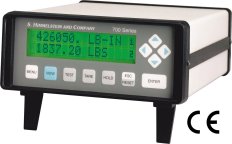
A two line alphanumeric display publishes measured and computed data, units of measure and test status. Transducer calibration is automatic, requiring no manual adjustments.
|
| Features
- 2000 Samples/Sec./Channel, 0.5 To 5 Mv/V And High Noise Immunity
- 6 Digit Engineering Unit Display With Legends And 0.01% Resolution
- 7 Pole Antialias Filter And 4 Pole Digital Filters With 10x Oversampling
- Real-Time Cross Channel Calculations And Math Operations
- 18 Built-In Data Acquisition And Control Functions
- Rs232, Rs422 Or Rs485 Serial Communication
- User Assignable Logic Inputs And Outputs
- Auto-Scaled ?5v And/Or ?10v Analog Outputs
- No Pots, Batteries, Fans, Maintenance, Or External Power Supplies
- CE Market
|
Compatibility
These instruments are compatible with virtually any 80 to 2000O strain gage bridge, ac or dc excited. They are particularly well suited for load cells, scales, pressure transducers, reaction, slip ring and rotary transformer coupled torque transducers.They are compatible with Himmelstein Torquemeter Models: MCRT 2800T Series, MCRT 28000T Series MCRT 2900T Series, MCRT 29000T Series MCRT 27000T Series Wheel Torquemetersand all earlier model Himmelstein Torquemeters. Please consult factory for verification of compatibility. |
| Specifications
| Transducer(s)
|
Type: Any 80 to 2000.© strain gage transducer, directly wired or transformer coupled.
Connections: Provision for 4, 6, or 7 wire circuits.
|
| Maximum Cable Length |
500ft for transducer impedance >100.© and 200ft for transducer impedance <100.©. |
| Transducer Excitation |
3Vrms, 3030Hz ± 0.01% sine wave. Regulated, and short circuit protected. |
| Input |
Sensitivity: 0.5 to 5mV/V with 50% overrange; automatically scaled.
Impedance: 100M.© in parallel with 33pF. |
| Automatic Null Range |
In-Phase Signals: ±10% of Full Scale (with 50% overrange), "60% of Full Scale (with 0% overrange).
Quadrature Signals: ±1mV/V. |
| Auto Calibration |
Dual polarity shunt calibration with provision for CAL resistor feedback. |
| Spurious Signal Rejection |
60Hz: 120dB common mode, 100dB normal mode. Carrier quadrature: 60dB. |
| Antialias Filter |
200Hz, 7 pole Bessel response filter. |
| Low Pass Filtering |
4 pole Bessel response digital filters with 11 cutoff frequencies from 0.1 to 200Hz in 1-2-5 steps. |
| Signal-to-Noise Ratio1 |
@ 1mV/V F.S.: 86/76/66/62dB with 1/10/100/200Hz filters.
@ 5mV/V F.S.: 86/80/72/66dB with 1/10/100/200Hz filters. |
| Resolution |
0.01% of Full Scale. |
| Overall Accuracy |
(at 77oF/25oC) 0.02% of Full Scale, worst case. |
| Temperature Effects |
Zero: ±0.001% of Full Scale/oF (max); Span: ±0.001% of Full Scale/oF (max). |
| Display |
Type: 2 line by 16 alphanumeric characters, each 0.2" wide by 0.3" high. Backlit LCD with adjustable contrast.
Views: Select either 2 Channels, 1 Channel with Limit Status, or 1 Channel with I/O Status.
Data Displayed: Select from Current, Max, Min, Spread, Held data and Tare value.
Data Format: Engineering units with 6 digits (1-2-5 format) and 5 character user-entered legend/descriptor. |
| Number of Channels |
Hardware: Supports one (Model 701) or two input channels (Model 711).
Calculated: One (CH3). Choose from 26 formulas based on CH1, CH2, and a constant. |
| Response (per channel) |
Data Sampling & Max/Min Update Rates: 2000Hz (hardware channels), 50Hz (CH3 calculation).
Limit Checking Rate: 1000Hz (hardware channels), 50Hz (CH3 calculation).
Logic I/O Response Time: 1ms (hardware channels), 20ms (CH3 calculation).
Update Rate for each Analog Output: 1000Hz. |
| Control |
(All I/O functions can be OR=d in any combination. The pattern function adds ANDing capabilities.)
Input Actions/channel: Logic inputs, outputs, and internal Matrix signals control following actions. Tare, Clear Tare, Hold, Clear Hold, Reset Max/Min, Clear Latched Limits, Check Limits, Do Max/Mins, Apply %CAL, Apply &CAL.
Output Events/channel: The following events drive Logic outputs and internal Matrix signals. HI Limit, NOT HI Limit, IN Limit, NOT IN Limit, LO Limit, NOT LO Limit, At Max, NOT At Max, At Min, NOT At Min.
Three User-defined Patterns: Patterns drive Logic outputs and internal Matrix signals.
Patterns are based on Logic inputs, outputs, and internal Matrix signals. |
| Limit Checking |
Each channel has a HI and LO limit which may be latched or unlatched, absolute or signed, and with or without hysteresis. Select either Current, Max, Min, Spread or Held data for limit checking.
Limit violations on any or all channels can be set to trigger backlight flashing in any of the display view modes. |
| Four Logic Inputs |
(each with programmable function -- destination)
Type: TTL compatible, Schmitt Trigger, low-true with 47k.© pull-up. Input current is -100FA @ 0V.
Protection: to "130VDC (or 130VAC). |
| Six Logic Outputs |
(each with programmable function -- source)
Type: Open collector, low-true. Operating @ 24V (max) and 0.3A max sink current.
Protection: Short circuit (current and thermal limits) and overvoltage (0.5A fuse). |
| Serial Communication Port |
(user selectable as RS232, RS422, or RS485)
BAUD Rate: 300 to 38400. Maximum Cable Length: 4000ft (RS422/RS485), 50ft (RS232).
Maximum Number of Devices: 32 (RS485), 1 (RS232/422).
120.© Termination Resistors (RS485): user selectable for RXD and TXD.
RS422/485 Transceivers: Slew-rate limited, short circuit protected (current & thermal limits).
RS232 Drivers: Short circuit protected (current limit).
Serial I/O’s: Use a 9 pin D connector. They are ±15kV ESD protected and float (100k.©) with respect to Earth Ground.
Commands: Control of all modes, settings, and measurements. |
| Non-Volatile Memory Storage for System Settings |
EEPROM, batteries are not used. |
| External +5VDC Power |
(on I/O connector) 250mA, short circuit (current limit) and overvoltage (1A fuse) protected. |
| Dual Analog Outputs |
(each assignable to any of the displayed channels)
Output Impedance/Minimum Load Resistance: <1.©/10k.©.
Full Scale: ±5V or ±10V (user selectable). Resolution is ±2mV @ ±5V FS or ±4mV @ ±10V FS.
Overrange: ±8.2V @ ±5V FS or ±13.5V @ ±10V FS.
Non-linearity: ±2mV @ ±5V FS or ±4mV @ ±10V FS.
Overall Error (worst case, including temperature effects): ±5mV @ ±5V FS or ±10mV @ ±10V FS.
Filter: 100Hz, 5 pole Bessel response low pass filter.
Protection: Short circuit (current limit) and overvoltage (0.25A fuse) protected. |
| Size and Weight |
6.5" wide, 2.9" high, 8.7" deep. Weight is 3 pounds. |
| Operating Temperature |
+41oF to +122oF (+5oC to +50oC). |
| Input Power |
90VAC to 250VAC, 50/60Hz @ 25VA, max. Two 2A/250V fuses, line filter, and rear power switch. |
| Notes: |
1. The ratio expressed in decibels (dB), of Full Scale to noise spread. Measurements are made for a 1 minute interval using a 350.© bridge.
2. Specification is subject to change without notice. |
|
|