| Strain Gage Input
|
Any 80.© to 2k.© transducer, directly wired or transformer coupled. 4, 6, or 7 wire circuits are accommodated. |
| Transducer Excitation |
3Vrms, 3030Hz ▒0.01% sine wave. Regulated, and short circuit protected. |
| Sensitivity |
0.5 to 5mV/V with 50% overrange; automatically scaled. |
| Input Impedance |
100M.© in parallel with 33pF. |
| Automatic Null |
In Phase: ▒10% of F.S. (with 50% overrange), ▒60% of F.S. (with 0% overrange). Quadrature: ▒1mV/V. |
| Auto Calibration |
Dual polarity shunt calibration with provision for CAL resistor feedback. |
| Spurious Signal Rejection |
60Hz: 120dB common mode, 100dB normal mode. Carrier quadrature: 60dB. |
| Antialias Filter |
200Hz, 7 pole Bessel response filter. |
| Low Pass Filtering |
4 pole Bessel response digital filter with 11 cutoff frequencies from 0.1 to 200Hz in 1-2-5 steps. |
| Signal-to-Noise Ratio1 |
with 1/10/100/200Hz filters 86/76/66/62dB @ 1mV/V F.S. and 86/80/72/66dB @ 5mV/V F.S. |
| Resolution |
0.01% of F.S. |
| Overall Accuracy (at 77oF/25oC) |
0.02% of F.S., worst case. |
| Temperature Effects |
Zero: ▒ð"0.001% of F.S./ oF (max); Span: ▒0.001% of F.S./ oF (max). |
| Frequency Input |
Any uni-directional or bi-directional (quadrature) source including self generating and zero velocity magnetic pickups, optical encoders, flowmeters, etc. When used with bi-directional sensors, the conditioner outputs both direction and magnitude. |
| Input Impedance and Configuration |
Differential or single ended inputs. 100k.© differential, 50k.© single ended. |
| Input Threshold (keypad selectable) |
10, 20, 50, 100, or 200mVpk-pk (between inputs) or TTL. |
| Maximum Voltage |
▒130VDC or 130Vrms. |
| Input Signal Bandwidth |
0.001 to 200kHz (10 to 200mV pk-pk threshold), 0.001 to 400kHz (TTL threshold). |
| Display Ranges and Resolution |
Rangeless (use any F.S. Engineering Unit value) with 50% overrange. Resolution is 0.01% of F.S. |
| Low Pass Filter (keypad selectable) |
20kHz (-3dB) or none. This filter is not available for TTL inputs. |
| Response Time |
Greater of: 1 ms, typical (2 ms worst case) or the input pulse length. |
| Common Mode Rejection |
80dB (60Hz), 55dB (0 to 10kHz). |
| Low Pass Filtering of Sampled Data |
Unfiltered or 4 pole Bessel filter. Cutoff frequencies from 0.1 to 100 Hz in 1-2-5 steps. |
| Overall Accuracy |
0.01% of F.S. @ +77oF (+25oC), 0.015% of F.S. @ +41oF to +122oF (+5oC to +50oC). |
| Excitation Supplies |
+12V@125mA2 or +5V@250mA2. short circuit (current limit) and overvoltage (fuses) protected. |
| Maximum Transducer Cable Length |
500ft except 200ft for 100.© or lower strain gage transducers. |
| System Display |
2 line by 16 alphanumeric characters, each 0.2" wide by 0.3" high. Backlit LCD with adjustable contrast. |
| Views |
Select either 2 Channels, 1 Channel with Limit Status, or 1 Channel with I/O Status. |
| Data Displayed |
Select from Current, Max, Min, Spread, Held data and Tare value. |
| Data Format |
Engineering units with 6 digits (1-2-5 format) and 5 character, upper or lower case, user-entered legend/descriptor. |
| System Response (per channel) |
Data Sampling & Max/Min Update Rates: 2000Hz (hardware channels), 50Hz (CH3 calculation).
Limit Checking Rate: 1000Hz (hardware channels), 50Hz (CH3 calculation).
Logic I/O Response Time: 1ms (hardware channels), 20ms (CH3 calculation).
Update Rate for Each Analog Output: 1000Hz. |
| System Control |
All I/O functions can be ORĺd in any combination. The pattern function adds ANDing capabilities. |
| Input Actions/Channel |
Logic inputs, outputs, and internal Matrix signals control following actions. Tare, Clear Tare, Hold, Clear Hold, Reset Max/Min, Clear Latched Limits, Check Limits, Do Max/Mins, Apply +ð%CAL, Apply -ð&CAL. |
| Output Events/Channel |
The following events drive Logic outputs and internal Matrix signals. HI Limit, NOT HI Limit, IN Limit, NOT IN Limit, LO Limit, NOT LO Limit, At Max, NOT At Max, At Min, NOT At Min. |
| Three User-defined Patterns |
Patterns of Logic inputs, outputs and Matrix signals drive Logic outputs and internal Matrix signals. |
| Limit Checking |
Each channel has a HI and LO limit which may be latched or unlatched, absolute or signed, and with or without hysteresis. Select either Current, Max, Min, Spread or Held data for limit checking. Limit violations on any or all channels can be set to trigger backlight flashing in any of the display view modes. |
| Four Logic Inputs |
Each with programmable destination, protected to ▒130VDC or 130Vrms. |
| Type |
TTL compatible, Schmitt Trigger, low-true with 47k.© pull-up. Input current is -100.¼A @ 0V. |
| Six Logic Outputs |
Each with programmable source, short circuit (current and thermal limits) and overvoltage (fuse) protected. |
| Type |
Open collector, low-true. Operating @ 24V (max) and 0.3A max sink current. |
| External +5VDC Power (on I/O connector) |
250mA, short circuit (current limit) and overvoltage (fuse) protected. |
| Serial Communication Port |
(selectable as RS232, RS422, or RS485. Supports 32 devices on RS485 port and 1 device on RS232/422) |
| BAUD Rate |
300 to 38400. Maximum Cable Length: 4000ft (RS422/RS485), 50ft (RS232). |
| 120.© Termination Resistors (RS485) |
user selectable for RXD and TXD. |
| RS422/485 Transceivers |
Slew-rate limited, short circuit protected (current & thermal limits). |
| RS232 Drivers |
Short circuit protected (current limit). |
| Serial I/Oĺs |
Use a 9 pin D connector. They are ð"15kV ESD protected and float (100k.©) with respect to Earth Ground. |
| Notes: |
1. The ratio expressed in decibels (dB), of Full Scale to noise spread. Measurements are made for a 1 minute interval using a 350.© bridge.
2. Both excitation voltages can be used simultaneously with the following restrictions: 4.8 x (12V current) + (5V current) "d700mA AND 12V current "d 125mA AND 5V current "d 250mA
3 Applies to strain gage channel only. Frequency measurement is absolute with guaranteed accuracy and only requires user engineering unit scaling.
4. Specification is subject to change without notice.
|

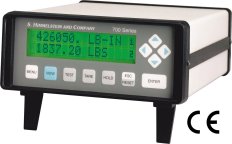 These advanced instruments provide engineering unit display of a strain gage (mV/V) input and a frequency input. They also compute power and perform 21 functions including limit checks, tare, hold, and max/min capture. You needn't write code or add hardware to be up-and-running a productive test.