|  The RPS-500 ranging board was designed to give analog voltage and current outputs proportional to distance and can be used with the RPS-100, RPS-300, RPS-325 or RPS-326. It is a fast, accurate means of converting analog pulse width generated by the ultrasonic sensor into analog voltage and current. Ranges available are 2" to14", 5" to 36", 5" to 72", 10" to 240". The RPS-500 ranging board was designed to give analog voltage and current outputs proportional to distance and can be used with the RPS-100, RPS-300, RPS-325 or RPS-326. It is a fast, accurate means of converting analog pulse width generated by the ultrasonic sensor into analog voltage and current. Ranges available are 2" to14", 5" to 36", 5" to 72", 10" to 240".
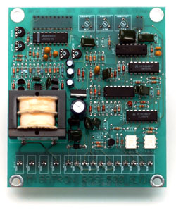
- Analog Ranging Card
- 2500 Volts Isolation
- 1 - 10 VDC Analog Voltage
- 4 - 20 mA Analog Current
- Ranges 2"-14", 5"-36", 5"-72",10"-240"
- Inverting Switch
- Zero, Span, Sample & Hold Controls
- 120VAC or 24VDC Power Input
ZERO & SPAN CONTROLS
The RPS-500 analog card comes with a zero and span control. These two potentiometers allow the analog signal to be adjusted over a desired range. The adjustment ratio is 5:1. This means that the RPS-500-14 (range 2" to 14") can be adjusted to give an analog output over a range as small as 2.4" or as large as 12". Example: If you desired a 4mA signal at 4" and a 20mA signal at 14" you would adjust the analog card as follows. Place a target at 4" and adjust the zero control until your current meter reads 4mA. Move the target to 14" and adjust the span control until you reach 20mA. With no more than two adjustments of each potentiometer the desired range will be achieved. If the analog card is in the inverted state, voltage and current decreasing with distance, the zero pot will adjust the 20mA point and the span pot will adjust the 4mA point. Always adjust the close point first.
INVERTING ANALOG SIGNALS
Both the current and voltage outputs of the analog RPS-500 card can be inverted. In the non-inverted state (switch 1 ON switch 2 ON) the voltage and current increase with distance. In the inverted state ( switch 1 OFF switch 2 OFF) the voltage and current decrease with distance. Note: The inverting switches should be set in the desired positions before begining adjustments with the zero and span controls.
SAMPLE AND HOLD
After each return echo the output voltage and current are updated. If no echo is received the previous readings are maintained or held. The time these readings are maintained will depend on the setting of the hold potentiometer, cw (up to 5 seconds). After this time has elapsed, the outputs will go to there maximum readings, indicating that there is no return echo. The advantage of this control is that it allows an echo or echos to be missed for a time without changing the output readings. This has proven to be advantageous in level control where the surface may be agitated.
LED DISPLAY
This 10 segment LED display will tell when a return echo is in the range of the sensor. For example, when the RPS-500 card is used with the RPS-300-14 and the target is 4 inches away just 1 or 2 LEDs will be on. When the target moves to 9 inches about 1/2 of the display will be on, and when the target is 14" away all the LEDs will be on.
ENABLE LINE
When the enable line is held high (high = 3 to 30V) the sensors will not transmit and the hold circuit will time out, causing the outputs to go to a maximum reading. A short time (Approximately 4.2mS) after the enable line is pulled low (low = 0 to 1V) the sensors will transmit. When a return echo is received the outputs will be updapted.
 |